 |
| August 06, 2013 | Volume 09 Issue 29 |
Designfax weekly eMagazine

Archives
Partners
Manufacturing Center
Product Spotlight
Modern Applications News
Metalworking Ideas For
Today's Job Shops
Tooling and Production
Strategies for large
metalworking plants
Picking the pattern for a stealth antenna

A frequency selective surface that acts as an RF filter and helps reduce the radar cross-section of antennas consists of a pattern of geometrical objects. There are literally thousands of possibilities, and testing each one physically would take enormous amounts of time. With simulation, though, we can find promising candidates in just minutes.
By Francesca De Vita, Simone Di Marco, Fabio Costa, and Paolo Turchi; Altran; Pisa, Italy
For roughly 30 years, the Altran Group has been a global leader in innovation and high‐tech engineering and consulting, providing services covering every stage of project development, from strategic planning through to manufacturing, to key players in the aerospace, automotive, energy, railway, finance, healthcare, and telecom sectors.
Antenna as the weak point
Our team works mainly in the aerospace and defense industry, and we have developed projects related to studies of antenna placement as well as radar cross-section prediction and control. One of them is addressing one of the largest leaps in defense technology developed in recent years: stealth airplanes and ships that avoid radar detection. They generally do so by combining several technologies including the shape of the target's surfaces to reflect energy away from the source and the use of radar-absorbent materials. However, if a ship's or aircraft's antenna is to operate properly it cannot be completely covered up -- and that makes it one of the remaining components with a large radar cross-section (RCS) and it can essentially destroy the overall system's invisibility to radar.
The RCS depends on the polarization and frequency of the incident wave. When an electromagnetic wave is incident on a target, electric currents are induced in the target and a secondary radiation from that target produces a scattered wave. The scattered field is partially reflected straight back to the source of the incident wave, and this is the principle upon which radar is based. The peak reflected wave is related to the standard antenna gain and its peak effective surface area. In this case there is an ironic twist: Antenna designers normally look to maximize antenna gain, but to lower the RCS they must do the opposite of what they normally do, specifically reduce the gain.
One way around this problem is to employ a frequency selective surface (FSS). It consists of a pattern of shaped holes or surfaces on a substrate and essentially creates a bandpass filter. In the intended frequency range, for instance where radio operators are transmitting or receiving, the antenna acts as normal; at other frequencies, the FSS absorbs rather than scatters incident radiation. Antennas are generally housed in a protective enclosure called a radome; for aircraft, often located at the nose. If that enclosure is made of such a FSS, its RCS is significantly reduced at all but the operating frequencies.
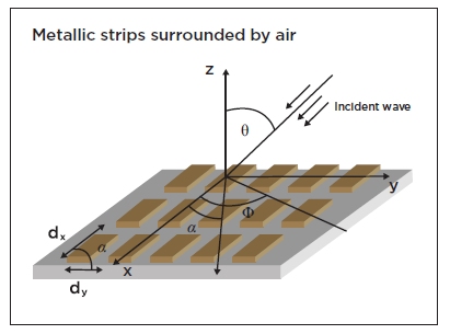
Figure 1: An example of a frequency selective surface (FSS) made up of a series of metallic strips.
Geometric patterns as a filter
Frequency selective surfaces are usually constructed from periodically arranged metallic patterns of an arbitrary geometry. They have openings similar to patches within a metallic screen (see Figure 1). The performance of a FSS is linked to its shape, thickness, choice of substrate, and the phasing between individual elements. We have focused on the physical configurations and the resonant frequencies for certain bandwidths. And COMSOL Multiphysics has been an invaluable tool in these studies.
As shown in Figure 1, a FSS consists of a series of geometrical objects. The FSS can be electrically large in terms of wavelength with very many instances of the object, which would make simulating the entire surface extremely cumbersome and expensive in terms of compute power and time. Luckily, COMSOL Multiphysics has a very convenient answer to this problem in the Periodic Boundary Condition (PBC) feature. It allows the simulation of a single cell unit and thus a less time-consuming process (see Figure 2). This feature provides for continuity of the electric and magnetic fields so we get equivalent results as if we had simulated an entire array of objects.
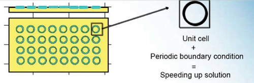
Figure 2: PBC functionality from COMSOL significantly speeds up the solution to our FSS study by simulating only a unit cell.
We were very impressed with the time and memory savings possible with a PBC while keeping the level of accuracy we needed to study the behavior of a given geometry. For a simple structure without a dielectric substrate, we estimate it cuts simulation time by a factor of 100; for a very large electrical structure, this could even be 1,000 times or more.
Figure 3 shows an example FSS made of simple metallic strips surrounded by air. The simulation mesh was created for one of the metallic strips, and you can see from the frequency plot that it has a passband in the region of 40 GHz.
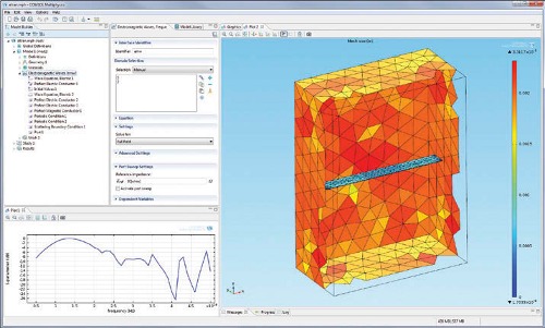
Figure 3: A simple example FSS based on a metallic strip array, with its meshed geometry (right) and frequency response curve (lower left). The latter shows the S11 parameter in dB and is at a scale of 1010 with a resonance at about 40 GHz. The dip corresponds to maximum transmitted power.
To validate our simulation, we first analyzed a case already dealt with in the literature and replicated the known results in COMSOL Multiphysics with the aim of tuning the simulation procedure. In a second step, we took this same validated simulation and modeled other types of FSS while changing geometries and materials and evaluating the impact of these changes on FSS performance.
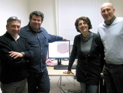
Altran's simulation team, from left to right: Fabio Costa, Simone Di Marco, Francesca De Vita, and Paolo Turchi.
We have used the software to investigate the frequency responses of a variety of simple shapes and sizes and how they are distributed on a surface. It is also possible to make the design more complicated by using two structures with complementary behavior. In this way we can, for example, create a design with multiple resonant frequencies. The ability to try any number of shapes highlights the capacity of the software to help us be efficient in finding a good solution. The alternative would be actually fabricating various shapes for the FSS and physically testing them, which would involve far more time and expense. With modeling, in a few minutes we can determine if a pattern is worth pursuing in detail.
We are now starting to expand our model to include the effects of the dielectric substrate. In addition, we hope to soon start working with optimization algorithms to help in cases where we face constraints such as maximum unit cell size.
Want more information? Click below.
Source: Republished with permission from COMSOL News 2013. Read more exciting COMSOL application stories at www.comsol.com/offers/comsolnews13/.
Published August 2013
Rate this article
View our terms of use and privacy policy